 |
| | Thread Tools |
| | #1 |
| [M] Reviewer Join Date: Nov 2004 Location: Waregem
Posts: 6,466
 | [FONT=Verdana]Have a look at this thread: http://www.xtremesystems.org/forums/...d.php?t=143275 As you can see: I managed to oc the k6/2 500 to an astonishing 720Mhz, using a 120Mhz front side bus. I really want to take this old skool oc'ing to the next level, but I'm limited to 120Mhz multiplied by 6 (bios maxed out). The only way to up the frequency is by upping the fsb or the multiplier. I believe the selection of multipliers can not be altered without modifying the bios, so there's only one solution left: front side bus modification! For years now, japanese overclockers always managed to get high fsb's. How? TurboPLL mods. I found a site which gave me enough information to understand how a PLL modification works: http://www.overclockers.com/tips745/ [/FONT] [FONT=Verdana]How A PLL Works:[/FONT] [FONT=Verdana]It gets an input frequency of 14.318 MHz and generates a number of frequencies out of it: fsb, pci, agp, floppy, usb ... [/FONT] [FONT=Verdana] [/FONT][FONT=Verdana]The base frequency of 14.318Mhz is generated by a crystal on the motherboard which produced exactly 14.318Mhz. If you up that frequency, you will up the front side bus, pci and agp clocks but also the floppy, usb and clock frequency! [/FONT] [FONT=Verdana]The modification will work, but soon you'll notice that the windows clock runs too fast and no usb works. [/FONT] [FONT=Verdana] What you want to let the modified PLL to do is just altering the FSB (maybe pci and agp) speed and leaving the other frequencies for what they are. [/FONT] [FONT=Arial, Sans-Serif] [/FONT] The next thing would be to start modifying ... that's where the problems kick in  . .If I understand right, I need to locate the PLL on my motherboard and find the pins that give the 14.138Mhz, the 24Mhz and the 48Mhz. Then I should remove the resistors from the lanes of those pins and the 14.318 crystal. Those elements will be replaced by the TurboPLL modification. Let's have a look at the chips on the P5A motherboard: - Chip above the socket: 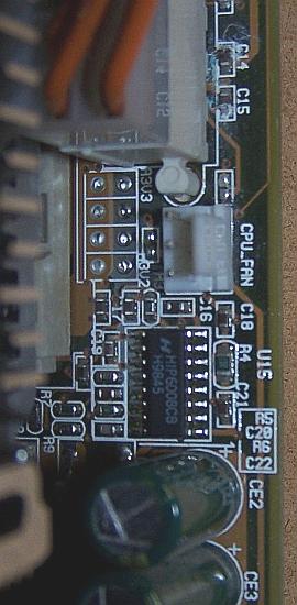 HIP6008CB H9845 - Chip near agp slot: 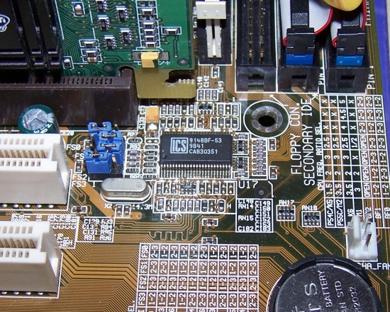 ICS9148BF-53 9841 CA830351 - Chips near bios chip: 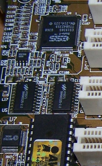 Probably not very important - Chip near chipset: 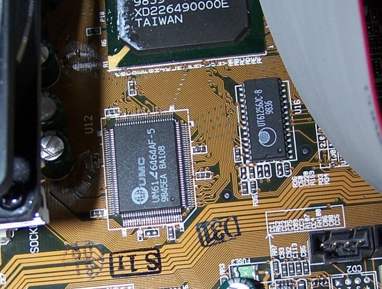 UT61256JC-8 9836 - Chip near memory banks: 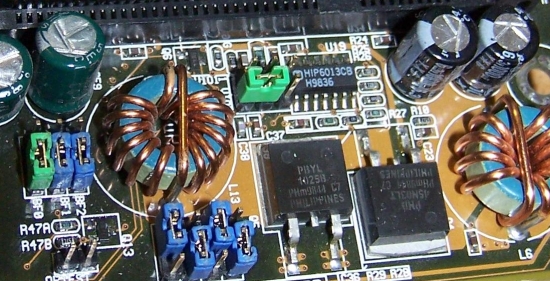 HIP6013CB H9836 What chip do we need? - The first chip is probably for the vCore, so we skip this (I already have the possibility the go to 3.5V and the chip doesn't really like much more than 2.9V) - The second is most likely the one we need if we want to mod the PLL. It has a crystal nearby and the datasheet shows us enough information. Pin25 is the 24Mhz, pin26 the 48Mhz. The only one missing is the 14.318 (clock) ... I guesspin46? - The third one is probably the vChipset regulator, but again, not 100% sure. - The last would then be the vDimm regulator? You see, a lot of probably and guessing here. Is there someone out here (I'm looking at you, Geoffrey  ) who's willing to help me figure this out? ) who's willing to help me figure this out? |
| |
| | #2 |
| [M] Reviewer Join Date: Nov 2004
Posts: 4,127
        | ICS was well know for their clockgenerators, the ICS9148BF-53 9841 CA830351 is the chip you're looking for. Check with your multimeter to know what is connected to eachother, just don't forget that inductors will also measure short because their resistance is very low. The 14.xxx MHz crystal should be connected between pin 4 and 5 of the ICS chip, but I never checked this so it could be possible that there are low ohmic resistors connected in between the crystal and the PLL IC. Furthermore, there are, or there should be, terminating resistors connected to every clock output, by removing those it should be possible to connect an external clocksignal. Now, I'll tell you straight away, this is not a job to be taken lightly. For Turbo PLL to work you must have a second clock generating source which provides you with stable 24/48 MHz clocksignals. This source could be an own build circuit, in most cases a second mainboard will do the job just fine, if trace lenght isn't that important.... Another thing which I didn't figure out yet is what exactly happens on system boot. The first main routines check how hardware is configured the hard way, programming resistors and jumpers are used to determinate the CPU host clock for example. Those 'switches' are connected to the PLL IC which has input ports, the logic level applied at those ports will have influence on the way your system is proceding in its boot process. The negative part here is that the inputs change into clock outputs once the PLL IC is completely programmed, and guess which pins they gave this dual input/output functioning... Though, by removing the terminating resistors (which is required when using external 24/48 clocksources) there shouldn't really be that much of a problem, I just couldn't figure it out yet if my way of thinking is going to give me te results I was hoping for. I can points you out what to do, but I'm not going to do this, I don't want to kill you are any others hardware because my thoughts do not match the reality. Now, even without the complete PLL modifications you can always just try to replace the 14.xxxMHz crystal and hope for the best. It takes about 5 min to test and another €cents to buy those components. I would also look for a crystal socket, this makes it easier to replace the crystals during benchmark sessions. |
| |
| | #3 |
| [M] Reviewer Join Date: Nov 2004 Location: Waregem
Posts: 6,466
 | And what about the vDimm and vChipset regulators? The problem with just replacing the crystals is the anomalities in benchmarks. My pi runs will be faster because the clock frequency runs faster. Those are no good benches (read: cheat). |
| |
| | #4 |
| [M] Reviewer Join Date: Nov 2004
Posts: 4,127
        | What about them? You were running out of FSB settings right? There should be another crystal in your board, problabe located close to the southbridge. If I'm not mistaken it oscillates at 32kHz and is used to make the real time clock so your Windows time shouldn't speed up as told above. |
| |
| | #5 |
| [M] Reviewer Join Date: Nov 2004 Location: Waregem
Posts: 6,466
 | vChipset and vDimm would come in handy when stabilizing the overclock. 120Mhz is the max overclock, but it's not 100% stable. I can't really see a crystal around the southbridge ...   |
| |
| | #6 |
| [M] Reviewer Join Date: Nov 2004
Posts: 4,127
        | Problabe, could have been somewhere else to  Full board overview pictures available? |
| |
| | #7 |
| [M] Reviewer Join Date: Nov 2004 Location: Waregem
Posts: 6,466
 | I'll shoot some tonight |
| |
 |
| Thread Tools | |
| |