NVIDIA Geforce 8800 Series Overclocking Guide

Howto by geoffrey @ 2007-05-18

In this in-depth guide we show you how the extract the highest performance from your Geforce 8800 video card, push that GTS past GTX speeds and turn that GTX into an Ultra-beater by following the steps outlined. We evaluate the performance increases along the way by using real world benchmarks; Can a $250 8800 GTS compete with a $500 8800 GTX? Read on to find out.

  • next

Intro & Tools Needed

Madshrimps (c)


Introduction

The last 6 months we had a chance to test a wide variety of G80 powered video cards; while we did overclocking tests in those reviews we thought it would be useful to dedicate more time on how exactly you can extract more performance from the Geforce 8800 video cards.

In this guide we’ll show how to find the maximum stable overclock speeds for both memory and GPU, as well as do more extreme volt modding to further increase overclocking potential.

To measure to impact of the overclock we test the performance at difference speeds to see how it scales in 3D applications and games.

This OC Guide has been made possible by Dollarshops.eu who provided with a
Sparkle 8800 GTS 320Mb Video Card to "play" with


Tools

Let’s discuss the tools of the trade:

  • RivaTuner
    - RivaTuner allows us to measure GPU temperatures, check GPU and mem speeds as well as shader clocks and of course overclocking.

  • nTune
    - nTune can force the Geforce 8800 fan to run at a specified value, setting it to full speed during benchmark/gaming sessions will improve cooling remarkably.

  • FutureMark 3D Mark
    - Futuremark’s 3DMark application allows us to stress the GPU and check for system stability;

  • Nibitor
    - This custom software is created for the sole purpose to edit the BIOS of NVIDIA video cards; which we can use to flash an altered BIOS with higher pre-overclocked values for GPU/MEM/SHADERS.

  • NVFlash
    - Time to hook up that old floppy drive (or modify your USB stick) to boot into DOS, as flashing the video card requires a clean “DOS” boot. NVFlash is the application which can write the new BIOS to the video card.

  • B2 pencil
    - A simple pencil can be used to increase the voltage fed to the G80 components if the correct bridges are “colored” in.

  • Soldering tools
    - We won’t go into much detail on how you should solder, but show you where to solder what. To get up to speed and tune your soldering skills please refer to our soldering guide

  • Multimeter
    - Essential piece of equipment to check the voltages once we start increasing them.

    Let’s start with the easiest and pain-free overclocking approach: through software, with Rivatuner ->
    • next
    Comment from MaK2000 @ 2007/05/19
    I would like to ask one thing. In Riva it shows that my card moves in steps but in nMonitor it shows what I have it set to in Riva. Which one is correct?
    Comment from blind_ripper @ 2007/05/19
    u card clocks in steps this comes treu bios , there is a bios that fixxes this . riva is always right
    Comment from MaK2000 @ 2007/05/19
    Where can I get a BIOS update? That kind of makes me mad at a $650 card. I have NiBiTor but modding the BIOS scares me. My card is XFX 8800GTX XXX. Where can I get an update?
    Comment from jmke @ 2007/05/19
    link and howto is in the... howto
    Comment from geoffrey @ 2007/05/20
    Last page there is a link attached to the EVGA bios, which enables overclocking per MHz (GTX!). You can download the latest BIOS updates at mvktech.net, though the situations that you would have to update your BIOS in order for your card to work properly are very rare.
    Comment from Carni4 @ 2007/06/05
    Hi guys. This is just a cheap way to keep your expensive hardware nice and cool. My temps dropped about 20°C

    I use rivatuner to set the fan speed to 100% (as mentioned in the article). Secondly, I have an Antec P180B which has a HDD case in the middle. I added the 120mm fan from the bottom of the case onto it which blows cool air across my videocard.


    I also added an Antec Super Cyclone blower. Which sucks hot air from the videocardcooler (videocard exhaust a lot of hot air through the slots on top of the cooler). Costs about $11,99 hardwareprice.net link


    I mounted the blower 1 slot lower then the 8800. So there's 1 slot space. I tried mounting it directly under the videocard but that didnt work.
    I know this blower takes up 2 pci slots, but for now I'm not going SLI anyways. When I do, I'll probably get two single slot blowers.

    The results:

    Room temperature: 19°C

    Default speeds Tempratures
    BFG 8800 GTS (513/792) no fan - no blower - rivatuner 60% 75°C
    BFG 8800 GTS (513/792) no fan - no blower - rivatuner 100% 65°C
    BFG 8800 GTS (513/792) fan - no blower - rivatuner 100% 60°C
    BFG 8800 GTS (513/792) fan - blower - rivatuner 100% 55°C

    Overclock speeds
    BFG 8800 GTS (600/1000) no fan - no blower - rivatuner 60% 79°C (I forgot to take a screenshot, but believe me it got HOT)
    BFG 8800 GTS (600/1000) no fan - no blower - rivatuner 100% 70°C
    BFG 8800 GTS (600/1000) fan - no blower - rivatuner 100% 64°C
    BFG 8800 GTS (600/1000) fan - blower - rivatuner 100% 59°C

    I hope you guys and girls can use this info.
    Comment from jmke @ 2007/06/05
    welcome to the forums , thank you for the informative post!

    I think you'll get better performance/noise results by swapping the blower for a 92mm fan positioned 45°C towards the card&rear with the PCI brackets removed; those blower fans have a very bad performance/noise ratio compared to normal axial fans
    Comment from geoffrey @ 2007/06/05
    Nice post there Carni4, thanks you for sharing your view on improving the stock GTS cooling.
    Comment from geoffrey @ 2007/06/11
    Small update, watercooling market:

    D-Tek FuZion GFX & UNI-Sink Combo- Geforce 8800GTX

    Heatsink and waterblock also appart available

    Swiftech Stealth


    EK waterblocks EK-FC8800 GTS - Acetal

    GTS version also avaible for GTX

    Zalman ZM-GWB8800 GTS

    GTS version also avaible for GTX

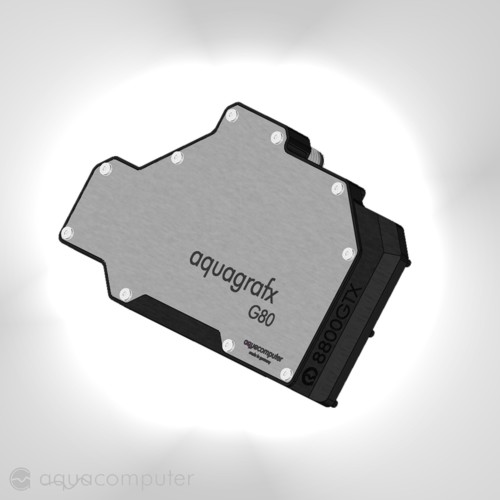
    Aqua-computer aquagraFX 8800 GTS

    GTS version also avaible for GTX

    Innovatek Cool-Matic G80-GTX/GTS
    Comment from geoffrey @ 2007/10/17
    Update, with new version of Rivatuner it is now possible to alter shaderclocks in windows, either linked to the core clock, or unlinked so that you never have to modify your BIOS again.

    Use Rivatuner 2.05 and Forceware 163.71.
    Comment from jmke @ 2007/10/17
    excellent
    Comment from geoffrey @ 2008/01/14
    Even now, manufacturers are still designing new heatsinks for G80 based videocards, look at this Arctic Cooling prototype that recently arrived at my bus:

    Comment from geoffrey @ 2008/01/14
    More hardcore modding available, Over Voltage Protection mod: http://www.xtremesystems.org/forums/...d.php?t=162124


    Past year I've been researching and exploring my skills in electronics, after long time, I had gathered the following info at our secure forums:

    Quote:
    Originally Posted by geoffrey View Post
    Introduction
    During my research for higher performance I've come across many different electronic schematics. Most of you know the existence of usual voltage mods and current protection tricks, let me tell you that for the NVIDIA 8800GTS we are having quite a hard time finding out what is holding back our overvolted cards. From what it seems, a over current protection kicks in whenever the GPU is heavy loaded (i.e. when high current is flowing through the GPU). The screen freezes and the PWM voltage module reads 0V. In order to know how we can fix this we must first understand how the PWM module exactly works and how the current sense network can be modified. For GeForce 8800 cards NVIDIA has chosen for the Primarion PX3540 PWM controller, here is a small schematic:


    For most people this won't look very clear, but let me tell you that this controller isn't that much different compared to many others I've seen, it only has more options and more PWM phases... Let's us first have a talk about how this type of voltage converter actually works.

    +12V

    Modern PC's have 3 common voltage levels available which feed most of its components, 3.3 Volt, 5 Volt and 12 Volt. Back in the old days the 3,3 and 5V line were used to feed the processors and DRAM modules, though over time the power usage of some modules become so high that is was in fact more attractive to use the 12V line as feed for CPU's and GPU's, it is much easier to supply high power at those voltage levels. Though, 12V is far beyond the maximum supply voltage for the high switching transistors found in modern microprocessors, therefore we needed a circuit which converted the 12V DC voltage coming from the PSU into the 1,5 Volt which is needed to feed the CPU. Such circuits are called DC-DC converters because they convert a certain DC voltage into a lower level DC voltage. Have a look at the following picture:


    The above picture shows a 12V DC power supply, a switch, a coil, a diode and a certain load which could be a lamp for example. The lamp will only light up whenever the switch is closed, that makes perfect sense to anyone. Now, if we rapidly set the switch to open and closes states, then the lamp will light on/off too, and if the on time is on par with the off time then the average voltage would be 12/2= 6 volt. If we would measure the voltage over the lamp we would see a square wave, something like this:

    _|-|_|-|_|-|_

    Now, in order to no longer switch on/off the lamp you could add a powerful coil in line with the lamp. Properties of coils tells us that they will work against the current flowing through them, therefore you will get a sawtooth kind of current flowing through your lamp, it will no longer have to switch on/off, we have created a kind of DC voltage though there is still lot of AC characteristic inside it. If you use your scope you will see something like this over you lamp:

    /\/\/\/\/\/\

    What the above picture doesn't show is the capacitors which are needed to filter the ripple out. After the coil one should add few capacitors, depending on their size the voltage measured over the lamp will become more or less a stable 6V voltage line. The caps aren't placed in line with the lamp but rather placed over the lamp, in parallel if that is easier to understand. You now will now have decent supply voltage which also could be used to feed CPU's, DRAM modules, ...
    In real life that switch isn't set on/off twice a second, but rather few hundred thousand times per second. We won't dive further into the whys here, you must only know that for this rapid switch we can't use human power to make the switch flip levels, nobody is that fast. We could use mechanical switches like a relais, though mechanical switches tend to have a very limited life cycle, after a month a relais could be burned for example. Mosfets on the other hand can be turned on/off almost unendless and are perfect for such operations, in computers we find N-type mosfets to switch the 12V line on and off.


    GPU nominal supply voltage

    In the above example we successfully converted 12V DC into 6V DC, but how can we build a DC-DC converter which is capable of delivering 1,5V on it's output? It's all in the name in fact... PWM, Pulse Width Modulation. With this technique we are going to change the on and off times of the switch/mosfet.
    In our above example we've switched the mosfet on for 0,5s, and switched it back of for 0,5s. The total wave length would be 1s, and the on state would be 50% of that total wave length, we speak of a duty cycle of 50%. Now, if we change the duty cycle to only 25%, then the mosfet would be switched off for 75%, and the average voltage would be only 25% of 12V -> 3V. If you understand well, the duty cycle defines the output voltage, the lower the duty cycle, the lower the average voltage, and the lesser light your lamp will create.
    Comment from geoffrey @ 2008/01/14
    More:

    Quote:
    Originally Posted by geoffrey View Post
    PWM modules explained

    To give you an idea of current PWM modules I've added a simplified connectivity drawing of the NX2415 PWM controller:


    You can see the 12V line coming from you PSU at the top right of the picture above. This voltage feeds dual mosfets who will do their own switching algorithm. If mosfet 1 is "on" then mosfet 2 will be "off" and so on. The mosfet have a special connection pin called the 'gate'. Applying a voltage at that gate will make the mosfet more or less resistance free, it will let the 12V voltage through. The pins on the PX2415 controller are therefore called gate drivers in most cases, because they will actually drive the mosfets on and off. Again you can see the coil which creates a sawtooth like voltage line which is being further rectified to a usable output voltage via big capacitors.
    In order to check whether or not the output voltage is good, each controller has a feedback loop which compares the circuit its output voltage against an internal set voltage. We won't dive any further into this, my main goal today was to focus on the over current protection circuit. New current sensing techniques learned us to add a RC-circuit (R from resistor, C from capacitor) parallel over the power coil, in this construction the voltage over the capacitor will increase in a linear way with the current flowing through the inductor. If we read this voltage back into our controller this means that we are actually reading in the amount of current flowing through our power circuit. Now look at the lower left side of the controller schematics... You'll notice a resistor divider which task is to set a certain voltage level at the OCP pin of the NX2415 controller. A resistor divider works as following: when you have a 5V DC supply, and you connect two 1k Ohm resistors in series between the + and - connectors of that supply, then you will get around 2,5V in between the resistors and ground. Depending on the size of those resistor, you will measure more or less voltage at that same point. If the first one has a resistance of 2k Ohm instead of 1k Ohm, then you will read less voltage in between the resistors and ground because more voltage has 'dropped' over the first resistor.


    That's how it works, this way we can change the reference voltage created inside controller to anything useful worth comparing with.

    Over current protection

    Like I said, the voltage over the Capacitor of the RC network is being read into the controller, inside the controller this signal is compared with the voltage level which we made at the OCP pin. The higher the current flowing through the inductor, the higher the voltage over the sensing capacitor (Cs), and the closer Cs will come to the voltage level applied at OCP, the over current trip point. After OCP has been tripped the controller will shutdown itself in order to protect itself against any damage and your pc will most likely freeze or reboot. We can work around this be changing the resistor values at the OCP pin, though we don't have any specific details about pin connections and functionality with the Primarion PX3540 PWM controller, we are forced to find out how the RC-network works so that we can manipulate the signal that is being read by the controller.
    Comment from geoffrey @ 2008/01/14
    Too bad I never found the time to test this modifications, anyway, I did dump my info on more experienced modding forums and everything seems to work like I thought. I have indicated the caps you need to be looking for, this picture is made from my G80 GTS. The GTX and Ultra might be a bit different:


    All you need to do is solder a resistor over each capacitors, you should be able to regulate OCP that way. As I said, I don't have any info on the resistor value's you should use, I never found the time to test this mod. That's why I do warn you, ONLY USE IT IF YOU ARE FAMILIAR WITH VOLTAGE MODDING, AND USE IT AT YOUR OWN RISK!

    Someone over at XtremeSystems recently tried my modification, that's why I decided it's about time to release my info, have a look at his thread:

    http://www.xtremesystems.org/forums/...d.php?t=171016

    Too small value's of resistor may influence the proper functioning of the PWM IC, therefore I would use 3 50k variable resistor and tune them down until you find the sweet spot for your Over Current Protection mod.
    Comment from geoffrey @ 2008/03/08
    Crysis is very demanding, in one of my gaming pc's the 7950GT is no longer able to feed my CRT with high framerates, so I though about dusting off the 8800GTS again. Off course, to give this card some extra breathing space, I wanted to go with voltmods again, an excellent opportunity to test out the only modification I haven't done until now. And man...

    ... this really is the modification that I've been looking for all the time! I can now run 720MHz core, 1800MHz shader and 1100MHz memory clocks at the same time, GPU voltmodded to 1,45V and memory up to only 2V.

    Took some fixed resistors and used the Galaxy Xtreme Tuner application to flash the videocard up to new hights, the AC Accelero Xtreme helps keeping the entire videocard at decent temperature:

    Stock: 500 / 1200 / 800
    [M]ad Overclock: 700(+40%) / 1800(+50%) / 1020 (+27,5%)


    I used 3 old 1kOhm resistors and soldered them in parallel with the capacitors I've mentioned above.

    For the GPU I soldered a 260 Ohm resistor from the Primarion chip to ground, and for the memory I used a 8,2 kOhm resistor from the memory PWM IC to ground.
    Comment from jmke @ 2008/03/09
    how the performance boost in Crysis stock vs OC
    Comment from geoffrey @ 2008/03/14
    Crysis 1024*768 4AA 16AF

    8800GTS 320MB stock: 48FPS
    8800GTS 320MB oc: 58FPS

    +20%, minimum FPS is the same, E2160CPU @ 2,4GHz on Via chipset.
    Comment from jmke @ 2008/03/14
    clearly no CPU bottleneck, pretty good numbers
    would drop AA and go for high res
    Comment from geoffrey @ 2008/03/14
    Quote:
    Originally Posted by jmke View Post
    clearly no CPU bottleneck, pretty good numbers
    would drop AA and go for high res
    17" CRT, it can't do better then that.
    Comment from geoffrey @ 2008/08/18
    Story continues:


    Water cooled, I'm currently running the 8800GTS 320MB (A2, old rev) at 760/1950/1080 through 3D Mark! With rev A3 this would mean close to 800 core I presume knowing the fact that the sample I have over here wasn't the best when it comes down to overclocking, this is all due to the modifications

    Core voltage is at 1,6V, Swiftech MCW-60 is performing quite excellent: GPU die temp doesn't pass 47°C!

    3D Mark 2003: 46504 http://www.hwbot.org/compare.do?resultId=763839
    Only 3k away from first spot, need stronger CPU, 5GHz Quad would help
    Comment from jmke @ 2008/08/18
    beating HD4870
    Comment from Massman @ 2008/08/19
    If you want to, I can lend you a E8500/E8600 to beat those scores
    Comment from Elijah86 @ 2008/10/20
    Thanks for the great guide.
    Comment from geoffrey @ 2008/10/20
    8800GTS travelling to Germany this weekend, if we have the time...
    Comment from jmke @ 2009/02/19
    seems all your studying paid off, you now hold the world record 8800 GTS 320Mb scores in all major benchmarks
    Comment from geoffrey @ 2009/02/20
    I wouldn't have settled for less
    Comment from JimmyJump @ 2009/11/10
    I've read the tutorial with interest, but I was hoping that the G92GTS would have been included.

    I've got an ASUS EN8800GTS-Top 512MB (G92) and all values on that one are different from the G80 models...

    By the way (and you all know this, but still), ASUS provides SmartDoctor with its cards, with which you can alter the shader clock separately, alas not by much.


    Anyway, I was wondering if there's a tutorial at hand for the G92GTS?
    Comment from jmke @ 2009/11/10
    I can recommend the latest version of Rivatuner which also support unlinked clocking; or if you like a slightly flashier version (but lose LOD tweaking and slightly lower limits): http://www.madshrimps.be/vbulletin/f...xplored-66627/
    latest version available from MSI website http://event.msi.com/vga/afterburner/
    Comment from JimmyJump @ 2009/11/10
    Quote:
    Originally Posted by jmke View Post
    I can recommend the latest version of Rivatuner which also support unlinked clocking;
    To say it with a little Meat Loaf: you took the words right out of my mouth... just downloaded RivaTuner from da Guru of 3D.

    I also located the different connections on the G92 pcb, should I choose to roll-up my sleeves and unleash a bolt of lightning unto the unsuspecting device.
    Anyway, should the national alarm level for small dust particles be raised, in combination with a substancial plume of smoke above the general area of 't Eilandje: no it's not the ESSO plant that has evaporated.

    Thanks jmke
    Comment from Massman @ 2009/11/10
    I'll be watching VTM, no, EEN news tonight!!
    Comment from jmke @ 2009/11/10
    if you post some high res pics of the PCB layout our local HW gurus can tell you what to mod for what, and what to look out for


    reply